This technique involves construction of loadbearing columns made from gravel or crushed stones that can share the load with the surrounding soil.

Common uses
Process
This technique emerged in 1957 when reinforcement of weak cohesive soils and mixed soils by means of stone columns was made possible using the Keller-made vibrator. By water jetting, the fines are flushed out and the liquefied annulus around the vibrator allows the coarse aggregate to sink in. By surging and electronic monitoring a well compacted stone column is constructed. The vibro-replacement process is now a well-established solution for soil replacement to large depths as it is cheaper and faster than the conventional methods that involve, dewatering, excavation and layer-wise compaction.
Wet top-feed method
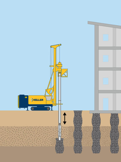
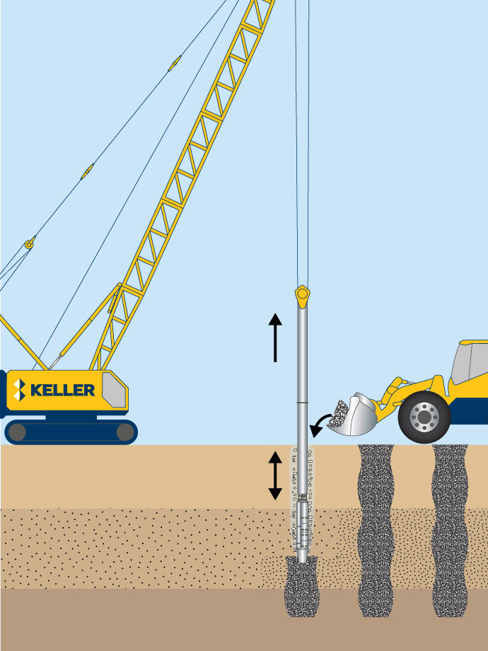
In the wet top-feed process, the vibrator penetrates to the design depth using the vibrator’s weight and vibrations, as well as water jets located in the tip. The stone (crushed stone or recycled concrete) is then added at ground level to the space around the vibrator created by the jetting water. The stone falls through the space to the vibrator tip, and fills the void created as the vibrator is lifted a few hundred millimetres. The vibrator is then lowered, densifying and displacing the underlying stone. This vibro replacement process is repeated in lifts until a dense stone column is constructed to the ground surface.
Dry bottom-feed method
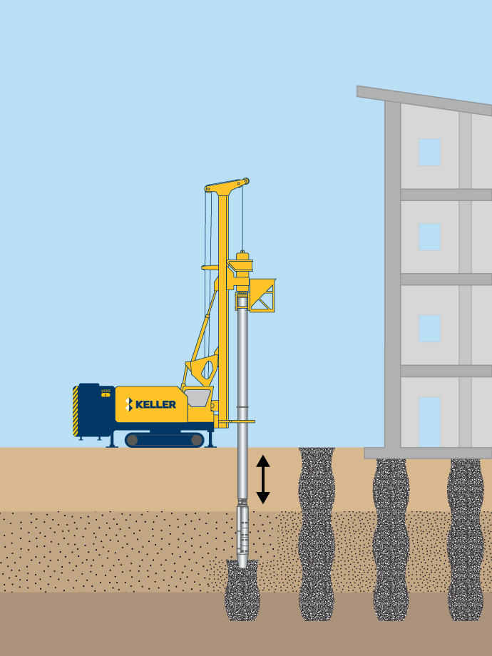
The dry bottom-feed process is similar, except that no water jets are used and the stone is fed to the vibrator tip through an attached feed pipe. Pre-drilling of dense strata may be required for the vibrator to penetrate to the design depth.
Vibro rigs can be fully instrumented with an on-board data acquisition system. Data from the system, such as amperage and lift rate, can then be recorded and displayed in real-time alongside specified target values on an in-cab monitor. This monitoring allows the operator to correct any deviations in real-time during the construction process to keep the vibro compaction within project specifications.
Variations on the product include vibro concrete columns where concrete is pumped into the ground through the vibrator, and grouted stone columns where the aggregate is mixed with a cement based grout on installation.

Wet top-feed method

Dry bottom-feed method
Advantages
Quality assurance
The vibro equipment we use is designed and manufactured by our in-house equipment manufacturer exclusively for use by Keller companies.
In-house quality production manager software enables us to capture and analyse data in real time and valid the performance of the ground improvement being carried out.
A variety of production parameters are generally logged during execution including depth, current, pull down force, uplift/pull down sequence, time and date and element number.
Field trials can also be used to verify column production parameters, along with static load tests, single or group, column material compressive strength tests, and column diameter verification.